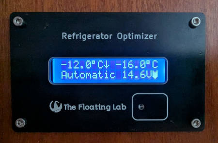
This is a generic instructional page about she self assembly of The Floating Lab projects with a 1602 LCD. There are multiple projects that all have this same common structure. Depending on the product you have a specific dedicated main circuit board and a front panel, but the rest of the components are the same.
Preparation
To successfully complete this project you need some basic soldering skills. Assembly of the kit is not difficult, but the order of the steps below is very important! Resist the temptation to just start soldering the "obvious" parts already together, doing things in the wrong order will make completion of the project (nearly) impossible!
You don't need many tools for this project:
- Soldering tool. This should ideally be in the range of 25-40 Watts. Soldering irons of 100W or more are not suitable for this task.
- Solder wire. Any solder wire with flux inside is acceptable. Only use solder wire that is intended for electronic work.
- Small wire cutter, to trim off the excess of the LED pins.
Inspect the kit
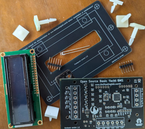
Check that the kit is complete. Most of my kits have a similar composition. The basic kit usually contains:
- 1 Main circuit board
- 1 LCD panel
- 1 Front panel
- 1 bezel
- 4 stainless steel alan bolts and nuts
- 3 sets of 6 pin headers (you will either install the SPI or FTDI pin headers but not both)
- 3 short mounting feet
- 4 long mounting feet
- 1 3mm flat head LED
- 1 resistor or piece of wire
Connector decisions
The connectors are the first items that need to be placed. After the LCD has been placed, you can not access the solder locations for the connectors anymore!
SPI connector
You need to install the SPI connector (2x3 pins) if your kit has not been pre-programmed, and you don't have a programmer with pogo-pins. If your kit has been pre-programmed, you don't need to install the SPI header. You might want to install the FTDI connector instead.
The SPI connector has a footprint of 2x3, so you will have to break one of the 6 pin headers into two 3 pin parts. The best way to solder these pin headers is to put them in place, hold them with a finger but don't touch the upper pin, then solder the upper pin. If you are satisfied with the alignment you continue with soldering the other pins, otherwise you just resolder the top pin until you are happy with the alignment.
FTDI connector
If your kit is pre-programmed and you don't have an SPI programmer but want to upload modified software yourself with the Arduino IDE, you need to install the FTDI pins.
Wire terminals
Wire terminals are not supplied in the kit versions because you might have other plans. It is also one of the reasons you received a discount. You can solder the connection wires directly onto the Printed Circuit Board, or if you want to box the kit, solder wires to a multi-pin connector installed through the wall of the box.
If you want to solder wire terminals on the PCB anyway, you should do that before you install the LCD. The terminals should have a 5mm pin spacing.
Terminals are available in 5.00mm pin spacing and 5.08mm pin spacing! The difference is small, but if your terminal has 8 connections, the misalignment adds up to more than half a millimeter.
Identify the sides of the Printed Circuit Board
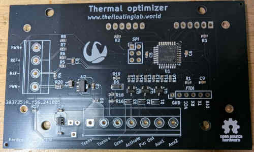
We named he side with the components the component side. This is the side where we install the pin headers and terminals, except for the pin headers of the LCD.
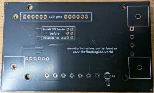
The side without components is named the LCD side. This is the side where the Liquid Crystal Display will be mounted.
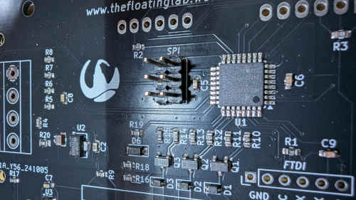
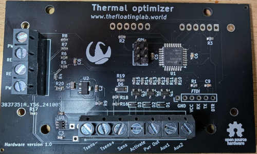
Install the connectors
Again: Install the SPI or FTDI pin headers and wire terminals before installing the Liquid Crystal Display, but do not install the LCD pins yet.
Install the Liquid Crystal Display
The Liquid Crystal Display (LCD) will be installed on the LCD side.
Double check that you have all desired connectors installed onto the circuit board and that they are soldered properly. After installation of the LCD the solder joints will not be accessible anymore! Removing the LCD afterwards is practically impossible.
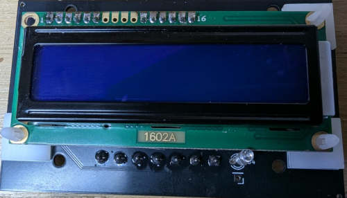
You have two different lengths of self adhesive mounts. You need the three short mounts for installing the LCD. Peel off the tape of the self adhesive feet and place them in the marked positions. One corner of the LCD has no mount but instead the connector pins are used for the support.
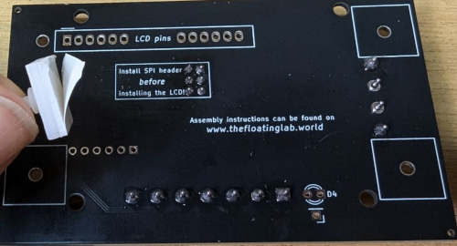
The LCD has 16 terminals, but we don't use the middle 4. Before pressing the LCD on its mounts, you should place the pin headers into the "LCD pins" marked location. Stick the short ends into the main circuit board. Do not solder them yet!
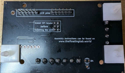
Press the LCD onto its mounts, and guide the connector pins through the LCD terminals. They are not soldered yet, so there should be some wiggle room.
Once the LCD is fully seated on its mounts, it is time to solder the connector pins. Don't put pressure on the LCD when you solder the first pin, keep care to maintain the correct alignment between the LCD and PCB. Once the first pin is soldered on both ends, double check the alignment, once you proceed the alignment is solidified and soldering the rest of the pins doesn't change the alignment anymore.
After the pins of the LCD have been soldered, place the LED in its place, but don't solder it yet! The LED has a long leg and a shorter one, the long one goes through the round hole. This is important, if you reverse the legs the LED will not work.
You can now remove the protective plastic film from the front of the LCD.
Install the front panel
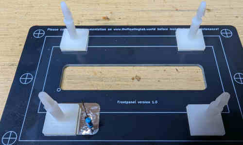
Attach the remaining four mounting studs onto the marked locations of the rear of the front panel. One location overlaps with the touch sensor, this is ok.
Solder the resistor or piece of wire onto the touch sensor pad. If you use a resistor, keep the touch pad leg as short as possible. The best way is to bend the leg 90 degrees close to the resistor, leave the bent part 3mm or so, and solder it to the touch sensor part.
Double check that you have removed the protective plastic film of the LCD, it will be more difficult to remove after the front panel has been placed.
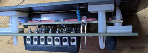
Guide the resistor or wire through the PCB, make sure the LED is not in the way, then click the front panel into place.
Finish
The only thing left is to guide the LED through the hole in the sensor pad. Try to get it flush with the front of the front panel. Depending on the tolerances of the LED, it can be a tight or loose fit. In the latter case, if the front panel is lying on a firm table top the LED will be automatically flush with the front panel and can be soldered in place. If it is a tight fit, try to push the LED in far enough. but it doesn't have to be all the way through. Do not try to make the hole bigger! The sides of the hole are conductive and connect both sides of the sensor pad together, reaming or drilling it would destroy the connection.
Solder the LED legs and the touch sensor wire. Trim off the excess.
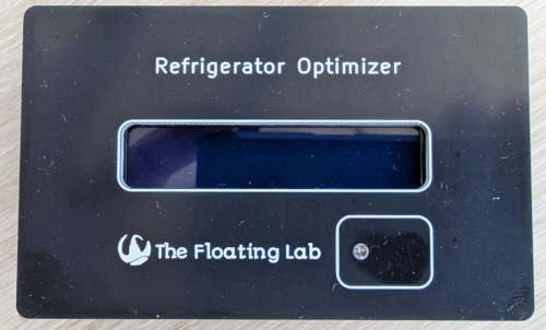
Time to dust off the front panel, build it into a panel, and admire the result!
If your kit has been pre-programmed it should come to live when you connect it to a power source, but if it has not been pre-programmed nothing will happen.
