Conversation in Fakarava
How much is a dive per person?
150
Ok, but we bring our own equipment, so no labor and wear for you. How much is it then?
150
Well, we don't need any guides or whatsoever, we only would like to have a ride on your RIB to the release spot, how much would that be?
150
Ok, we will use our own dinghy. How much do you charge for just only refilling our dive tanks?
150
To scuba dive on your own in the Pacific you really need your own dive compressor. You typically won't find dive shops on uninhabited atolls and on places where they have dive clubs (like on Fakarava) the dive clubs want you to dive with them, rather than using them to refill your tanks. While there is added value for diving with a local dive club, there comes a moment where you want to dive on your own and this is only possible when you have your own dive compressor.
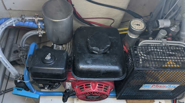
We bought a used but well maintained Maxair dive compressor. This brand also sells under the name Coltri. They are made with electric motors and gasoline engines. We try to use fossil fuels as little as possible, but after doing some math we realized that operating a dive compressor on our 1500 Watt of solar power input would be very difficult. People who have a dive compressor with an electric motor typically run their generator to power the dive compressor, so either way you are ending up burning some fossil fuel to fill the dive tanks. Since we sold our generator we had no other choice than to buy a gasoline driven dive compressor.
Modifications for stationary use
These dive compressors are intended to be used outside, but this has a few disadvantages:
- You don't want to keep the compressor outside all the time, so this means that this heavy piece of equipment must be moved outside every time you want to use it, and afterwards needs do be stored inside again. For many people it is a health hazard trying to get 40Kg's of equipment through a hatch or going up some stairs on a (possibly moving) boat.
- Having it outside to let it perform its job exposes it to rain, UV, possible salt spray and increases the risk of theft.
The dive compressor already has a place inside the boat when it is not being used, so why not operating it exactly there from its own place? A few modifications were necessary to make this possible.
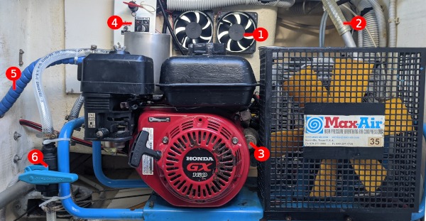
The best place for our dive compressor was the starboard engine room. There was a shelf where once the air conditioner was installed and this shelf was exactly the right size for our dive compressor. Also we liked to have this beast in the engine room, after all it is sort of an engine and it smells like gasoline and oil, produces dust from the drive belts, etc. and the only place where we tolerate that is in an engine room.
Cooling
Cooling is the major challenge. The engine, exhaust and the compressor itself produces together a lot of heat. If you think about it, you are actually burning the consumed fuel inside the area where the compressor is located! I installed two big fans behind the compressor to suck out the hot air via the unused starboard life raft compartment and when we operate the compressor the engine hatch remains open to allow plenty of cool air to enter. After a while we converted the exhaust into a wet exhaust, see below which significantly reduced the heat release inside the engine room.
Air inlet
As we don't like "engine room air" inside our dive tanks we drilled a hole through the engine room wall into the living compartment, in our case our bedroom, and route the air intake through it. If the air in the bedroom is good enough to keep us alive during one third of our live, it must for sure be good enough to keep us alive for the maximum 1 hour we stay under water. This also separates the engine room from the air intake, so that any leaking exhaust fumes, belt dust or other bad stuff can never reach the air intake. Our bedroom is "upwind" of the engine room when we are at anchor, and we open a deck hatch in the bow when we run the dive compressor to scoop lots of fresh air into the hull.
Electric starter
The space in the engine room makes it not really practical to pull the starter cord so we opted for an electric starter. Mind you, this is not a factory option of the dive compressor, but it is really easy to implement nevertheless. The Honda engine that drives the compressor is a generic engine which is also used on a variety of devices like lawnmowers, generators, carts, etc. and some of these devices have electric starters. On Amazon we found a "conversion kit" for less than 100 USD.
Electric start conversion kit, available at Amazon.
I earn a small commission if you buy it via this link, thanks for supporting me!
Installation turned out to be easy; our Honda engine already had the mounting lugs and mounting holes for the electric starter. We had to cut a small piece from the engine cover and from the side of the guard grid from the fan of the compressor unit, but then the starter fitted nicely in the space between the Honda and the compressor unit.
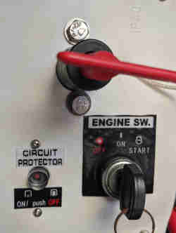
The conversion kit comes with some coils that comprises an alternator to charge its supposed starting battery, but we don't use a dedicated dive compressor battery but just start the dive compressor from the boat's service battery bank. We don't need the dive compressor to pay back the little power it used for starting, neither are we going to use the dive compressor as a contingency battery charger, so I didn't bother to install the charge coils. There is no space to mount the small starter panel on the side of the engine cover, so I took the supplied panel apart and installed the starting key and thermal fuse on a separate box on the wall, in the same box where we also installed the battery switch.
Compressor drains
The compressor drains need to be opened frequently to drain the water out. You can collect this tiny amount of water in a bottle or route the hose outside. Note that the drains contain tiny particles of the silicon oil that lubricates the compressor, so make sure that the drain blast doesn't touch any structure you might want to (re)paint in the future. Silicone is notoriously difficult to remove and makes future paint jobs very problematic.
Making the compressor drains to open automatically every 5 minutes or so is high on my wish list, however I haven't found any suitable electrically controlled valve that can handle 250 bars. Another solution would be to use a small electric motor to drive the drain valves automatically, but some other higher priority projects need to be finished first.
Exhaust
Initially we welded a so called "flexible" exhaust tube on the outlet of the standard muffler and routed it outside of the engine room, with the tube ending just below the bridge deck to take advantage of the passing air to take the fumes away. This worked very well to get rid of the exhaust fumes with no easy way back to the interior of the boat, but the exhaust didn't live very long. It was very exposed to sea water and apart from becoming rusty in a short time, some upslams of seawater went into the exhaust tube and seawater found its way into the combustion chamber of the poor Honda. After a few months not having used the compressor we discovered that the engine had seized. I had to replace the piston and piston rings to get it going again.
There was another reason why we were not so happy with the exhaust: it released a lot of heat into the engine room. One time when we were operating the compressor just after sunset we saw that the muffler and first piece of the tube were glowing red. We suspected that the major source of heat of the dive compressor was the exhaust. It was time to start thinking about a different solution.
Wet exhaust
A standard marine solution for combustion engines is to embed the exhaust manifold into a seawater filled container, often combined with the heat exchanger for the coolant. Water can absorb tremendous amounts of heat and is readily available on a ship. The Honda engine however has no water cooling and water cooled exhausts didn't appear to exist already. So we had to design something ourselves. We wanted to keep it simple because we have no welding equipment and were depending on commercial welders to put it together. The more complicated it looks, the higher the quote.
The design goals where to:
- Cool the exhaust tube as close as possible to the engine. Closest to the engine is where the exhaust tube exhibits the brightest red hot color so the closer to the engine it is cooled down, the less heat is released.
- Prevent upslams reaching the combustion chamber. This could be done with a valve but it might get stuck so it is better to have some kind of a water collector space with a drain.
- Mix the exhaust fumes with seawater to cool them down sufficiently so they can be released via a rubber hose.
- Dampen the sound as much as possible. Dampening the sound could be achieved by an "expansion room" to flat out the pulses and by cooling down the fumes. The sound of an exhaust is the result of the expansion of the air caused by the combustion, cool the fumes down and the air contracts to its normal volume and the sound largely disappears.
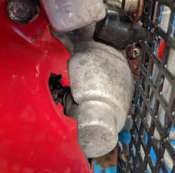
My design only works in situations where the dive compressor is installed above the water line and the exhaust hose doesn't has to rise after leaving the "muffler".
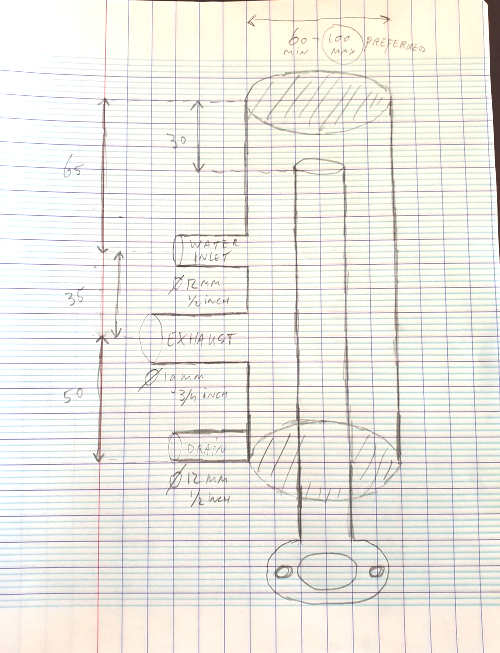
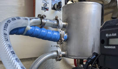
The exhaust roughly fits into the same space as the original muffler. The first part of the exhaust tube is submersed into seawater, then releases the fumes in the space above the sea water which is our "muffler" to dampen the exhaust pulses. Sea water is sprayed in via the side, just above the exit, so that the fumes have lots of contact with the sea water on their way out. The remainder of the spray touches the exhaust tube and the inner walls of the "muffler", and then remain in the pool to cool the first part of the incoming exhaust tube. The exhaust fumes and excess of seawater are dumped overboard via the marine exhaust flexible hose, a small portion of the water is drained via the bottom connection to prevent the accumulation of salt and to drain away seawater that might get slammed into the exhaust by a rogue wave.
The connections:
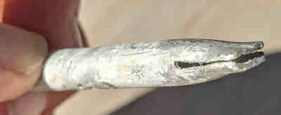
- Water inlet. The source of the sea water is our existing sea water pump installation that also provides sea water for the galley, toilet, and high pressure deck hose. We only need a small amount of water for the exhaust cooler, so we installed a restrictor in the feed hose. Inside the hose I installed a small aluminium tube, flattened the end in a vice so that it sprays a nice wide but flat stream of water inside. You will have to test and adjust this spray so nothing of the water sprays against the top or it would drip into the engine exhaust. Of course this would do no harm as long as the engine is running, but the dive compressor will shut down automatically when it reaches it target pressure and then the exhaust cooling is still running.
- The exhaust hose. We used the smallest marine exhaust hose we could locally find, which was 19mm (3/4"). The hose can be looped slightly upward to make a "water lock" but we didn't find it necessary. The water comes out as a spray together with the fumes and is not too hot to touch.
- The drain. The connection at the bottom is used to slowly drain the pool when the compressor is not in use. This gets rid of the salt residue and also the water from upslams which collects here is drained away before the level would rise high enough to overflow into the engine. I used a restrictor in the drain hose so only a small amount flows out when the compressor is in use while remaining sufficiently large to drain the sump when the compressor is not in use. The drain is connected to an existing nearby bilge pump through hull.
The mentioned restrictors are made by putting a smaller hose inside the outer hose and then a hose clamp to squeeze the hoses until the desired stream remains. You could use standard valves as well, but this increases the number of hose connections and valve positions are too easily readjusted inadvertently.
The test procedure would be like this:
- Test the feed restrictor and aluminium injection tube outside of the muffler. It should give a nice wide spray pattern without too much splashing (pressure).
- Mount the hoses but leave the exhaust disconnected from the engine. Open the feed valve and and adjust the restrictors so that only a small amount of water flows out via the bottom drain and the majority of the water flows out via the exhaust exit hose. Make sure that no water drips down via the exhaust tube running down to the engine. If this happens there is too much splashing inside and you should reduce the pressure and/or change the spray pattern. Also make sure that the exhaust hose always stays lower than the top of the inner exhaust tube.
- Connect the exhaust to the engine and let it run. The temperature of the water coming out of the exhaust hose should not be too hot for the touch, otherwise increase the amount of water going in. Check the amount of water going out of the drain. Due to the temperature of the water the hose may soften and the flow might change, readjust if necessary.
It is a good idea to buy one of these standard thermostat switches to interrupt the ignition wire when the temperature of the exhaust becomes too high. This could happen when for some reason the flow of seawater is interrupted and in that case the thermostat prevents melting of the hoses and other hazards. A thermostat switch of 150 Celsius would be good for this job.
The result
I have no way of knowing whether the spray pattern works as I intended, how exactly the sound is dampened, and whether the design could be made simpler, but at least all my goals are met:
- a very noticeable reduction of heat inside the engine room
- a much quieter exhaust
- no rusty and dangerously hot parts anymore
- the final exhaust is an easy to route low temperature flexible hose
- no risks of upslams reaching the combustion chamber anymore
- it should be just as durable as any other marine exhaust installation.
Mission accomplished!
Lots of effort goes into the free information pages and services of this website. If you want to show your appreciation and support my efforts, you are welcome to contribute with a donation to my personal Paypal account.