This is a very basic but functional Battery Management System for Lithium batteries, built on the Arduino architecture. It can be used as a stand alone BMS but also as a redundant watchdog BMS to overrule the primary BMS if it fails to detect or act upon a cell voltage excursion event.
Objective was not to build a fully fledged BMS, but to build a BMS with as few external parts and libraries as possible. Some friends blew up their BMS while sailing in the South Pacific, I quickly had to cobble something together to help them out, without external parts that would take months to become delivered.
Luckily I'm working on a major BMS project, so I could take some tested and proven source code from it to quickly develop this basic BMS.
- Features
- How it is done
- Parts needed
- Options
- Configuration, Programming and Calibration
- Installation
- Usage
- Assembled version
If you randomly arrived on this page via a search engine, note that this BMS was developed for lithium installations on ships, which are typically built with LiFePo4 cells between 300Ah and 1000Ah. On a ship, there are usually no separate charge and discharge events but the battery is charged with the loads connected. This BMS is specifically designed to be used in these challenging conditions. Although this BMS would perform equally well on smaller cells, and/or systems with a separated charge and discharge cycle, some comments and directions will not apply to your situation.
Features
- If any cell voltage drops below 2.70V, the lithium battery will be disconnected until the bus voltage becomes higher than the battery voltage.
- If any cell voltage climbs above 3.45V, the lithium battery will be disconnected until the bus voltage drops below the battery voltage.
- Suitable for single bus and dual bus topologies (Dual bus is with separated charge and consumer buses)
- Reconnection delay to avoid rapid cycling
- Automatic calibration of the resistor dividers
- Automatic reset after software and hardware errors by use of a watchdog timer
- Low power consumption
- Very few external parts
- Very low costs
- Easy to build
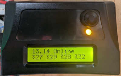
- Optional LCD display with continuous cell voltage monitoring
Some features are lacking by design:
- No detection of SoG (State of Charge). For this a current sensor would be needed to count all the amps going in and out of the battery. This would require parts which are not commonly available and is therefor out of the scope of this project.
- No reporting facilities. A web interface, a bluetooth connection to a mobile phone app, NMEA or CAN interface, this is all outside the scope of this project, which objective is to build a functional BMS with as few external parts as possible.
- No "range limiting", the full range from 0-100% of the battery capacity is used. To limit this (which would be beneficial to the life expectancy of the lithium cells) it would be necessary to monitor the SoG, for which a precise current sensor would be required. To be honest, no BMS's are capable of doing this as far as I know, except for my flagship BMS I'm developing. So, this AruinoBMS is switching off the lithium battery when either 0% or 100% of the capacity is reached. These are the only two points that can be reliably detected by cell voltage monitoring. To learn more about this subject, read my article about lithium battery management
- No balancing. With good cells, balancing is not needed for several years. So, for a contingency or watchdog BMS, as this project is aimed to be, balancing is unnecessary.
- No support for 24V systems. The Arduino simply lacks enough ADC ports to measure 8 cells plus a bus voltage, and because of the higher voltage a higher resistor divider ratio would have to be used, reducing the measurement resolution by a factor 2.
- No temperature sensor. Lithium batteries should not be charged below freezing temperatures! Most sailors sail in the tropics, but if you sail in arctic conditions you have to be careful not to charge the batteries when they are below freezing temperature.
Working with lithium batteries can be dangerous, as they can release tremendous amounts of energy in a very short time. If things go wrong there is a risk of fire and/or explosions. It is your own responsibility to judge whether this project is suitable for your particular installation, and whether you master the skills to build this project and safely install it.
How it is done
At first I thought that building a functional BMS couldn't be done with just an Arduino alone. The resolution of its ADC is small, becomes even smaller with the necessary resistor dividers, the resistor dividers introduce imprecision and the reference voltage is unstable as well. At the same time the Arduino consumes quite a bit of power in its standard configuration.
But I found solutions to each of these problems, and in the end I had a BMS that could do the job. Let's look into a few of the solutions I came up with.
Resistor dividers
The Arduino can measure voltages up to almost 5V, while the voltage of the top lithium cell can rise up to 15V. All ADC inputs are single ended and thus referenced to ground. We therefor need a resistor divider to bring the cell voltages down into the ADC measurement range. In practice, the lowest cell could be measured without a resistor divider, but the higher cells would need a resistor divider with a higher ratio for each higher cell. Dividing the voltage means that also the resolution is divided, so we don't want to divide more than necessary. For the top cell, 1:3 would give enough reserve also for voltage spikes. However it makes no sense to have different measurement resolutions on each individual cell, so I use a 1:3 resistor divider for each individual cell. This allows for more consistent measurements and less chances for mistakes.
To deal with resistor imprecision, I wrote an automatic calibration routine. To calibrate the resistors, the 4 cell voltages and bus voltage are all connected together to the 5V rail. Since all voltages are then supposed to be equal, ArduinoBMS is then able to work out a calibration factor for each resistor divider so that the measured values becomes exactly 5V. These calibration values are then stored in the EEPROM of the Arduino and will be used for all future voltage calculations.
The resistor dividers however introduce a small problem: the leak current through each divider not only runs through its own cell, but also through all cells below it. This means that cell 1 will see not only the current of its own resistor divider, but also from all the cells above it, while cell 4 only sees its own current. This has no consequences for the measurement, but it will slowly throw the cells out of balance. You might think that a leakage current of 0.5mA is not much on a cell of, let's say, 400Ah, but if you do the math you will discover that 0.5mA accumulates to more than 4Ah per year. To prevent this, cells 2, 3 and 4 are progressively loaded with a balance resistor so that all cells end up with the same leak current.
ADC resolution
The standard Arduino BMS has a resolution of 10 bits. With a 5V reference voltage, each step is 4.88mV. With a 1:3 resistor divider the resolution would become 14.64mV at the sensor inputs. Add to this that the Arduino has a gain error of up to 2 steps, the reference voltage also has some imprecision, and all this together means that we will end up with something that is not terribly precise anymore. However, we can use a trick: Oversampling. By oversampling the ADC resolution can be cranked up to 13 bits, resulting in a resolution of 1.83mV at the sensor inputs. Now we are talking! It doesn't come for free however: Tradeoff is that for 3 bits more resolution 64 samples are needed for just a single ADC reading. The Arduino however has not much else to do, and we don't need a cell voltage measurement in a split second, so the time required to perform all these measurements is not going to be a problem.
Reading multiple samples in a live system however introduces a potential problem: During the collection of the samples a heavy load may come on line, or (with solar or wind based chargers) a cloud may appear or the wind might die. This changes the voltage abruptly, and while it is still good enough to obtain an average reading, it spoils the oversampling. So the program starts to read a resolution of 10 bits, then cranks it up step by step to 13 bits. If a series of readings are suddenly clearly different than the average, then obviously something happened on the charge or discharge side, these readings are then rejected and the bits collected so far are used instead.
ADC frequency
Oversampling requires noise in the system, also called "dithering". The (maybe counter intuitive) science behind it is beyond the scope of this article but can be easily found on the internet. Luckily we can expect some noise in a live system, and a way to introduce even more noise in the system can be achieved by increasing the sample rate. This also reduces the time spent collecting the samples needed for the oversampling, so this is a win-win. ArduinoBMS therefor doubles the ADC frequency. This is the sweet spot, if we would go even higher we are going to start loosing precision.
Reference voltage
The Arduino ADC by default uses the 5V power supply as a reference. Problem is that this voltage reference is not designed to be used as a reference and can indeed be quite unstable, depending on load, temperature and input voltage. An alternative would be to use the internal 1.1V reference, which is not calibrated but at least very stable, but then the Arduino can only measure voltages up to 1.1V, which means that we need a resistor divider of at least 1:14 instead of 1:3. This would drop the measurement resolution considerably.
Test results when loading the 5V supply with and without an LED (loaded and unloaded), to see how small supply variations will affect the ADC readings. Input was measured on a small Lithium cell.
| Test condition | Unloaded V | Loaded V | Difference |
|---|---|---|---|
| Without correction | 3.598 V | 3.626 V | 0.028 V |
| With correction | 3.591 V | 3.586 V | 0.005 V |
The trick I use is to measure the 1.1V internal reference with the ADC while the ADC itself uses the 5V reference. The 1.1V reference is not precise, but that doesn't matter, what matters is that it is very stable. The measured value should therefor always be the same, so if a different value is measured this is due to variations in the 5V reference. This way the relation between the precision reference and the power supply reference can be established. Before every cell voltage reading the 1.1V reference will be sampled and if the relation to the 5V reference has changed, a new voltage calibration correction factor is calculated and applied on the next ADC readings of the respective cell. I deliberately varied the 5V reference and it turned out that the automatic correction works amazingly well!
Reliability
Although this BMS is simple and cheap, it is highly reliable. Quite healthy margins are used towards the cell voltage limits, so even small measurement errors and imprecision will not lead to exceeding the limits. These larger margins might reduce the available charge with a few percent, but actually this is a good thing as it promotes a longer battery life.
The programming code is straight forward, so any software freezes are highly unlikely, but nevertheless, a watchdog feature is used that will reset the processor if a certain "check point" is not passed in the code every 4 seconds. This watchdog feature is a piece of circuitry in the processor that runs independently from the main processor core.
The processor also resets itself when its power supply voltage drops below a certain value.
Power requirements
The ArduinoBMS uses only a few milliAmps, but on a ship all tiny savings help. The best way to reduce the power consumption of the Arduino would be to reduce the power supply voltage. However we can't do that as we use the 5V as an ADC reference. If we lower the voltage, this means we also have to have a higher ratio in our resistor dividers which would spoil the resolution again. Also it would be more difficult to control an LCD and the relay outputs. Therefor I kept the voltage at 5V.
I've chosen for another power saving approach: keep the processor in sleep mode as much as possible. The standard Arduino "analogRead()" function is "blocking", i.e. the processor asks for an ADC conversion and waits until the result becomes available. I wrote a new ADC routine that puts the processor immediately into sleep mode after the ADC conversion request is made, then fires an interrupt when the ADC result becomes available to wake up the processor again. This reduces the power consumption dramatically, as most of the time will be spend waiting for ADC readings, and this is now with the processor in sleep mode. There is relatively little computation needed in this program, so the processor now spends the majority of its time in sleep mode.
Another power saving feature is that in case of a low voltage disconnect, the BMS goes into a deeper power saving mode: It powers down everything and wakes up briefly only once every 8 seconds to see if there is a charge current available.
It is also possible to reduce the power further by lowering the clock frequency. For this you need to have more low level programming tools and/or install another bootloader. This is beyond the scope of this article but it can be done if you have the tools and know what you are doing.
It is possible to save even more power by removing the builtin LED's from the Arduino circuit board, but that would void your warranty. ;-) Personally, I don't care for some LED's lightening up the inside of a sealed enclosure at the expense of some precious juice, so I routinely remove them, but that's just me.
Parts needed
The objective was to use as few external parts as possible. Let's assume you have some assortment of resistors, beside these, you need the following, depending on the options you select:
Arduino
The source code will run on any 168 or 328 based Arduino, like the most common Arduino Uno. We only use the features of the processor itself, so you don't need a more fancy board. But although the source code runs on a basic Arduino Uno R3 development board, I recommend an even simpler Arduino pro mini. The Uno R3, being a development board, has a convenient DC power regulator and USB connector, but this causes it to use quite a bit more power than the Arduino pro mini. Even in sleep mode, the USB circuitry continues to use 10mA, which doesn't sound like much, but this is by itself already a quarter Ah per day. Especially after a low voltage disconnect, when the lithium battery is supposedly empty, this is a lot and can damage the battery if a charge current remains absent for a few more days. The pro mini is also smaller and cheaper than its larger siblings. Then again, if you happen to already have an Arduino Uno around, and never drain your battery for more than a day, the Uno R3 can do the job. You can "upgrade" to a pro mini later.
You can buy an Arduino pro mini on Amazon.
I earn a small commission if you buy it via this link, thanks for supporting me!
The 5V regulator on the Arduino pro mini however is whacky, it will eventually release the smoke at any input voltage over exactly 12V, so you must use an external 5V regulator instead. This can be a simple 7805, but also one of these very cheap but efficient DC/DC convertors you can find nowadays in online shops, allowing you to save more than half of the power required.
You can also use these DC/DC convertors to power your Arduino UNO directly on its 5V pin to save more than half of the power it normally requires with its builtin linear regulator.
Efficient 12V+ to 5V DC/DC converter, available on Amazon.
I earn a small commission if you buy it via this link, thanks for supporting me!
The Arduino pro mini has no USB connector, so to program it you will need a FTDI programming module. If you use the larger Arduino UNO, you don't need a programming module.
FTDI programming module, available on Amazon.
I earn a small commission if you buy it via this link, thanks for supporting me!
Resistor dividers
You will need some resistors to bring the max 16V down into the ADC measurement range. Luckily they don't need to have a high precision, as the software can automatically calibrate them.
If you change the resistor values, make sure to also change the resistor values in the header file. I wouldn't recommend to go to a ratio under 1:3, but a ratio higher than necessary progressively reduces the measurement resolution. You need to account for imprecision of the resistors, so keep a healthy margin to stay into the measurement window with all expected voltages. Also avoid making the inputs too high impedance. I think the values I have chosen in the schematic are the best option.
For safety, I recommend to connect the resistors R1-R5 as close to the cell terminals as possible. This way the leads coming from the cells can never conduct more than a few milliAmps. If you would put all the resistors on your PCB, you would have to run "hot" wires from each cell to your PCB, and when a short circuit occurs, well, with lithium batteries the results are often a bit more spectacular than just a puff of smoke...
Balance resistors
The balance resistors have no effect on the working of ArduinoBMS and are therefor optional. However, the asymmetric loading of cells by the resistor dividers will cause the cells to loose balance over time. To compensate for this, a balance resistor can be placed over the cells, so that all cells are seeing the same leak current.
If you change the values of the resistor dividers, you also need to change the values of the balance resistors.
- The balance resistor R11 parallel to Cell2 should be (R1+R6)
- The balance resistor R12 parallel to Cell3 should be (R1+R6)/3
- The balance resistor R13 parallel to Cell4 should be (R1+R6)/6
Relays
There is no point in building this BMS if you don't give it a way to disconnect the lithium battery when a cell voltage exceeds its limits. In an emergency setup, and with low currents, a simple car relay could do the job. But the maximum current would be limited and you will need to feed constant power in the relay to keep it engaged. But with nothing else at hand and with the objective to keep the navigation equipment and some LED lights working, this could bring you home. Note that the software is able to reduce the power to keep a mono-stable relay engaged by using PWM.
A much better option however is to use a bi-stable high current relay. Bi-stable means that it has two coils, once pulled open or closed it stays that way, until the other coil is briefly powered. Hence there is only power used during the transition from one state to the other.
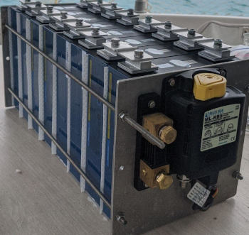
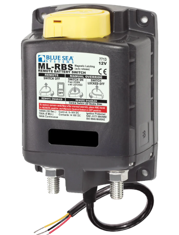
The best bi-stable relay I could find is the "Blue sea remote battery switch". It is intended as a remote switch, consisting of a command switch and a bi-stable relay. We don't use the command switch, we leave the commanding part to the ArduinoBMS. The relay can handle 500Amps continuously, has a manual override (handy in case of problems or maintenance), and the best thing is that it can be controlled directly by an Arduino output. No other components are needed!
Blue sea remote battery switch (relay), available on Amazon.
I earn a small commission if you buy it via this link, thanks for supporting me!
If you are building an emergency BMS, chances are that you can salvage the relay from the dead BMS. But if your lithium battery is mission critical (and it probably is), I would only leave shore with a spare relay anyway.
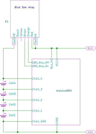
Note that the "plus" of the relay is connected to the voltage bus, not to the plus of the lithium battery! In case of a low voltage disconnect, you want to re-power up the lithium battery from the bus, not from its empty cells!
Housing
Housing is not critical, but try to find something that is waterproof. Most hardware stores sell electric junction boxes, they are fine for the task. If you use the optional LCD, best is to have a clear housing so you can mount the LCD inside. The frames of the LCD's tend to rust if you leave them exposed to the open (salty) air.
Options
Push button
This is a momentary switch, and can be used to manually stop or (re)start the BMS. If you use the "Blue sea remote battery switch" you don't need the switch for this purpose, as a manual override is already builtin into the relay.
Relay control outputs
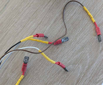
If you use the "Blue sea remote battery switch", you can connect the relay directly to the Arduino and it is reasonable to build this project without a PCB. As already explained, it is best to mount R8-R12 as close as possible to the battery and bus terminals, the same applies to the balance resistors, so there will be only 5 resistors left to connect to the Arduino, and you can incorporate them in some nice way into the wiring. Shrink tube is your friend!
You can skip the rest of this section if you use the "Blue sea remote battery switch".
To build the relay control output(s) you are going to need a Printed Circuit Board (PCB). If you use an Arduino pro mini you can solder the Arduino right onto the same PCB. If you use the Arduino Uno a nice way is to buy a prototype shield that can be stacked onto the Arduino itself. The one I selected also incorporates the switch.
Arduino prototype shield, available on Amazon.
I earn a small commission if you buy it via this link, thanks for supporting me!
Also, you need to check that the relay has a diode across its coil terminals. If not, you need to add it yourself.
The MosFet should be a TTL compatible N-channel MosFet, such as the FQP30N06L.
10-pack of FQP30N06L, available on Amazon.
I earn a small commission if you buy it via this link, thanks for supporting me!
Also, note that the ground of the MosFets is not shared with the ground of the Arduino. The relay(s) draw a lot of peak power and if the ground is shared with the Arduino, the cell voltage readings will be influenced.
Optional LCD
If you want to use the optional 1602 LCD display, make sure it is one without an I2C interface soldered on. We can not use an I2C interface because the I2C output of the Arduino is shared with one of the ADC inputs, which we need for measuring the voltage. Also, I prefer the yellow-green LCD's over the blue ones, as the former uses less power for the backlight and is even readable without the backlight.
2-pack of 1602 LCD, available on Amazon.
I earn a small commission if you buy it via this link, thanks for supporting me!
ArduinoBMS provides a (PWM) output for the LCD backlight. The default behavior is that the LCD backlight goes on after a keypress or a mode change, then turns off after 5 seconds of inactivity. Instead of just "on" or "off" you can control the LCD brightness with a PWM value. This however will prevent the processor to enter sleep mode as long as the PWM output is active. It is therefor better to play with the backlight series resistor until you achieve the desired brightness in "full on" mode. If you want to have the LCD background just dimmed in the inactive state but not completely turned off, instead of assigning a low duty cycle PWM value, it is better to assign a zero value, and feed a small current to the backlight with a bypass resistor directly connected to the 5V rail. This is possible because ArduinoBMS switches the brightness output to an input during inactivity so it becomes high impedance. So by carefully selecting the resistors you can avoid having to resort to PWM to achieve the desired active and inactive LCD backlight brightness.
Configuration, Programming and Calibration
First you have to download the software package.
The software and hardware schematics of this project are maintained at git.thefloatinglab.world, you can download the most recent version there.
Edit the header file "ArduinoBMS.h". Pay attention to the relay configuration and other settings.
How to program an Arduino depends on the chosen Arduino model and programming interface, and there are plenty of tutorials already on the internet, so I refer to one of those if this is your first project.
Once you programmed the Arduino, it is time to power it up for the first time. This is best done on the bench, not yet installed into the live installation.
Connect all cell terminals and bus voltage terminal to the 5V line before powering up the Arduino. This will automatically invoke the calibration mode. You can repeat this process as many times as you like.
Calibration should take a few seconds. After this, the Arduino will go into "monitor mode" where it will display the measured cell voltages. This will be output on the Serial output as well as on the optional LCD.
If you want to power up the Arduino with the programming interface connected, disable the 5V output that comes from the programming interface (USB) and use the 5V power supply of your Arduino instead! You want to calibrate against its own 5V power supply, not against the (temporary) programming 5V supply!
Optionally: If your 5V power supply differs from 5V, as measured with a reliable multimeter, change the CALIBRATION field in the header file so that the output matches the voltage as precisely as possible.
Most standard multimeters have a DC precision of 0.5%. This means that if you measure the reference voltage of 5V, it could just as well be 4.95V or 5.05V. For the charge termination of the lithium cells, it could mean that instead of at 3.5V you actually terminate at 3.535V. Add some imprecision of the Arduino itself and you get close to the chemical cell limit of 3.6V. It is best to check the voltages with a high-end multimeter.
Installation
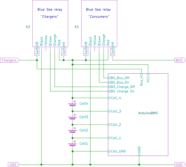
The installation depends on whether you have a single bus or dual bus configuration. If all chargers and consumers are connected to a single bus, you have a single bus installation. This is definitely the case when you have not already a (former) lithium installation. In a single bus installation it is highly advisable to keep a lead acid battery connected to the bus, to function as a buffer when the lithium battery goes offline.
If you have all the chargers connected to one bus, and all the consumers on another bus, you have a dual bus configuration. Although ArduinoBMS is designed to work with a dual bus installation equally well, I recommend converting into a single bus installation, because it is more robust, safe and fault tolerant.
If unsure, consult my article about lithium implementations. In my opinion, the best installation is the hybrid-installation, where you have a single bus and a lead acid battery as a buffer to complement the lithium battery, so the latter can safely be taken offline when the BMS deems this necessary.
General remarks
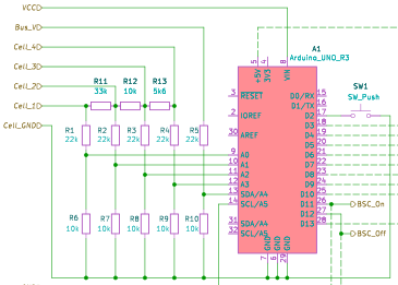
I didn't show the resistors in the lines to the cell junctions, but I recommend that you don't put the top resistors of the resistor dividers on the PCB but instead connect them as closely as possible to the cell terminals. This prevents the wires running to your PCB to carry any significant current. If you want to put these resistors on the PCB anyway, I recommend to install fuses in the wires between the cell junctions and the PCB.
I didn't show fuses in this schematic diagram. But in general, all "hot" wires should have a fuse that melts before the respective wire does. In my own setup, I have a 1A fuse in the power supply to the BMS, and a 5A fuse in the supply to the relays. My lithium battery itself has a 400A fuse.
You might notice in the schematic diagram that there are two GND connections and two BUS connections. Although it looks like you could save some wiring by connecting the respective "double" connections together directly at the Arduino, don't do it! Run a separate wire for the Cell-GND and connect this wire directly at the cell 1 minus terminal. The same applies to the BUS connections: run a separate wire for the Bus voltage sensor to a suitable terminal on the power bus. The reason for this is that the (optional) LCD and relay control circuitry use some power. Especially the relay control circuitry can momentarily demand a high current. If you share this with the ADC sensor lines, you will influence the voltage readings. This becomes worse with longer and thinner wires.
Dual bus installation
In a dual bus configuration, the lithium battery should be connected to a relay controlling the charge bus, and a relay controlling the consumer bus. If the lithium battery is full, the charge bus will be disconnected, if the lithium battery is empty, the consumer bus will be disconnected. The lithium battery stays always connected to either the charge bus or the consumer bus.
Apart from the extra relay, a few things have been changed:
The Arduino power supply is now connected to the lithium battery itself, as there is no lead acid battery to act as a backup. In case of a low cell voltage disconnect, the Arduino will put itself into a low power sleep state, only waking up briefly every 8 seconds to check the bus voltage to see if some charge power becomes available.
The same applies to the power of the relays. They are now connected to the lithium battery, as it is the only place likely to have some power.
The bus voltage monitor is now relocated to the charge bus. We don't need it on the consumer bus because the voltage there is always equal to the lithium battery voltage, or zero when the consumer bus is disconnected. But on the charge bus, when the lithium battery is full and the charge bus is disconnected, we want to know if the charge voltage disappears or reappears so we can restore the connection.
Monitoring mode
If you hold the push button during startup, ArduinoBMS will go into cell monitoring mode, where it just displays the measured cell voltages and does nothing else. To enter this mode you will have to press and hold the button before connecting the power supply. To exit this mode, you have to power down the BMS.
Usage
Upon startup, it will disconnect (if not already so) the lithium battery from the power bus, and (by default) enter "Pause" mode. In the software, you can also opt for starting up in "Online" mode instead. Obviously, if you don't install a push button, this is what you want.
Note that if the LCD backlight is dimmed, when we are talking about button presses, the first button press will be "used up" to switch the backlight on. You then have to press the button again (while the backlight is still on) to invoke the action associated with a "button press".
The BMS will always be in one of the following activity states:
- Pause
- By default, the BMS will startup in "Pause" mode, as if you pressed the stop button. In "Pause" mode, nothing will happen until you press the button to let it resume normal operation. When not in Pause mode, pressing the button will enter Pause mode.
- Pending
- This mode means that the BMS is ready to connect the consumer bus, and will do so in a few seconds. This mode is entered when the last disconnect event was less than 30 seconds ago. This prevents rapid cycling on and off. The connection LED will blink during this time.
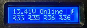
- Online
- The BMS is now connected to the consumer bus. The connection LED will be on.
- Full
- The lithium battery is full. In a dual bus installation, the charge bus has been disconnected. In a single bus installation, the lithium battery has disconnected from the bus. As soon as the voltage of the (charge) bus drops below the lithium battery voltage, or all cell voltages have dropped to a predefined value, the BMS will restore the connection and the status will change to "Online". Note that by pressing the button and cycling through the "Pause mode", the status of the cell voltages will be re-evaluated.
- Empty
- The lithium battery is empty and the consumer bus has been disconnected. The BMS is in power saving mode, only checking voltages once per 8 seconds. The (charge) bus will be reconnected when the bus voltage becomes higher than the battery voltage or when the cell voltages raise to a predefined level. Note that by pressing the button and cycling through the "Pause mode", the status of the cell voltages will be re-evaluated.
- Sys Err
- This error is displayed when a system error is detected, like an unrealistic bus voltage. This error can only be cleared by powering down the BMS. Investigate before rebooting.
- Cell Err
- This error is displayed when one or more cells are below 2.5 Volt. A lithium cell with a voltage below 2.5 Volt is broken and should be discarded. It is unsafe to use a cell that has ever been below 2.5 Volt, even if it seems to "recover". One of the tasks of a BMS is to prevent this from ever happening, by disconnecting the consumer bus before a cell drops too much in voltage. This error can be cleared by rebooting the BMS, but remember, a cell that has been allowed to drop below 2.5V will remain a safety hazard forever.
- Overvolt
- This error is displayed when one or more cells are above 3.6 Volt. This should never be possible: something is seriously wrong with the system. In a single bus installation, this could indicate a relay that is stuck in the closed position. In a dual bus installation, this condition might occur when a charger is connected to the consumer bus instead of to the charge bus. The BMS has no other choice than to disconnect itself from both buses. This error can only be cleared by rebooting the BMS. Investigate why it happened before trying again. The battery may have sustained damage, depending on the duration and severity of the voltage excursion.
- Ry Err
- This error is displayed when a problem is detected with the relay. This error is triggered when the relay is (supposed to be) closed but a predefined voltage difference between the bus and the lithium battery has been observed. The cause can be a faulty relay or too much loss in the connection cables. Voltage loss will translate into elevated temperatures in the lossy areas, potentially creating a fire. This error can be cleared by pressing the button, but please investigate the problem first.
No Display operation
If you don't have an LCD, you can instead connect two more status LEDs. Apart from the "connection LED" that is also used when you have an LCD, you will also have a "Full" and "Empty" LED, which will signal these two respective conditions. In case of an error, both LED's will light up at the same time.
In case of an empty battery, the "Empty" LED will only briefly flash every 8 seconds. This serves to minimize the power consumption on the almost empty battery. In case of a "Cell error", the "Full" LED will also flash at the same time.
You can not install these extra status LED's when you also use an LCD, because the extra status LED's use outputs that would otherwise be used by the LCD.
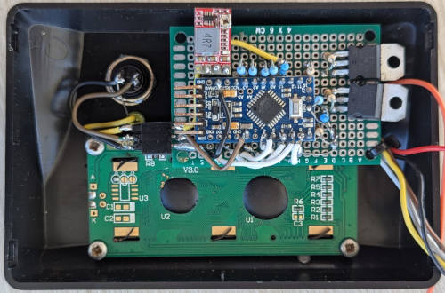
Assembled version
I'm considering to run a small batch of readily assembled ArduinoBMS boards. Apart from being assembled already, these would give a few additional benefits:
- All required components will be on the PCB.
- The boards will be equipped with an efficient DC regulator.
- The boards will be equipped with a header so an LCD can be directly soldered onto it without using wires.
- The boards will be equipped with a temperature sensor.
- The boards will operate at 1 MHz, instead of 16 MHz, reducing power requirements even further.
- The boards will be equipped with an alarm output.
- Relay output MOSFET's with protection diodes will be installed.
- An FTDI programming interface, as well as a SPI will be available onboard.
- The (modified) source code will be online available.
Drop me a note if you are interested. You can contact me on Matrix or via E-mail.
Lots of effort goes into the free information pages and services of this website. If you want to show your appreciation and support my efforts, you are welcome to contribute with a donation to my personal Paypal account.